Understanding the CAN Bus: The Backbone of Automotive Data Communication
The Controller Area Network (CAN) bus is a critical technology in modern vehicles, enabling seamless communication between various electronic control units (ECUs). From engine management to infotainment systems, the CAN bus ensures reliable, real-time data exchange. This article explores the history, architecture, and advantages of the CAN bus, compares it to other automotive communication protocols like LIN, and highlights why it dominates the automotive industry. Additionally, we address common questions about the CAN bus and explain how specialized software and devices for CAN bus data reading and analysis can unlock valuable insights for automotive professionals, enthusiasts, and developers.
History of the CAN Bus

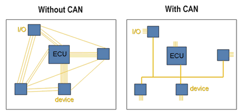
The CAN bus was developed in the early 1980s by Robert Bosch GmbH, a German engineering company, to address the growing complexity of automotive electronics. As vehicles incorporated more electronic systems, traditional point-to-point wiring became cumbersome, expensive, and prone to failures. Bosch aimed to create a robust, efficient, and scalable communication protocol for automotive applications.
- 1983: Bosch began developing the CAN protocol to standardize in-vehicle communication.
- 1986: The first CAN specification was published, supporting data rates up to 1 Mbps.
- 1991: The CAN bus debuted in production vehicles, notably in Mercedes-Benz models, marking its transition from concept to practical application.
- 1993: The International Organization for Standardization (ISO) adopted CAN as ISO 11898, cementing its global acceptance.
- 2003: The introduction of CAN FD (Flexible Data Rate) enhanced the protocol by allowing higher data rates and larger payloads, addressing modern vehicles' increasing data demands.
Today, the CAN bus is the de facto standard for automotive communication, used in virtually every modern vehicle and extended to industries like aerospace, industrial automation, and medical devices.

CAN Bus vs. LIN and Other Automotive Protocols
Automotive communication protocols vary in complexity, cost, and application. The CAN bus is often compared to protocols like LIN (Local Interconnect Network), FlexRay, and MOST (Media Oriented Systems Transport). Below, we outline key differences:
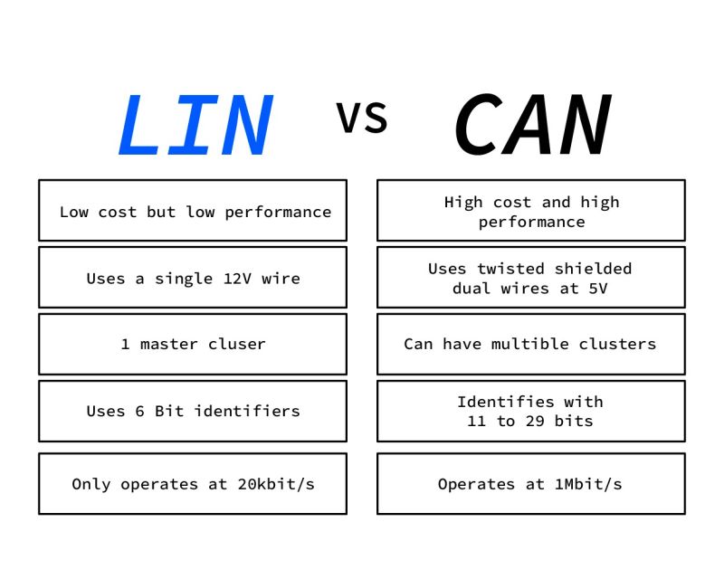
CAN vs. LIN
- Purpose:
- CAN: Designed for high-speed, critical systems like engine control, transmission, and braking. It supports multiple ECUs communicating in real time.
- LIN: A low-cost, single-master protocol for non-critical systems like window controls, seat adjustments, and climate control.
- Speed:
- CAN: Up to 1 Mbps (standard CAN) or 8 Mbps (CAN FD).
- LIN: Up to 20 kbps, significantly slower due to its simpler design.
- Cost:
- CAN: More expensive due to its robustness and complexity, requiring twisted-pair wiring and advanced transceivers.
- LIN: Cheaper, using single-wire communication, ideal for cost-sensitive applications.
- Reliability:
- CAN: Highly reliable with built-in error detection (e.g., CRC checks, bit stuffing) and fault tolerance.
- LIN: Less robust, suitable for low-risk applications.
CAN vs. FlexRay
- Purpose:
- CAN: General-purpose, widely used across vehicle systems.
- FlexRay: Designed for high-speed, deterministic applications like advanced driver-assistance systems (ADAS) and drive-by-wire.
- Speed:
- CAN: Up to 8 Mbps with CAN FD.
- FlexRay: Up to 10 Mbps, with a focus on predictable timing.
- Cost and Complexity:
- CAN: Lower cost and simpler implementation.
- FlexRay: More expensive and complex, used in premium vehicles for specific high-bandwidth applications.
CAN vs. MOST
- Purpose:
- CAN: Focuses on control and sensor data.
- MOST: Optimized for multimedia and infotainment (e.g., audio, video).
- Medium:
- CAN: Uses copper twisted-pair wiring.
- MOST: Often uses fiber optics for high-bandwidth multimedia data.
Why CAN Dominates
The CAN bus is the most widely used automotive protocol due to:
- Versatility: Suitable for a wide range of applications, from critical systems to diagnostics.
- Reliability: Robust error-handling mechanisms ensure data integrity in harsh automotive environments.
- Cost-Effectiveness: Balances performance and cost, unlike FlexRay or MOST.
- Scalability: CAN FD extends its capabilities for modern vehicles with higher data demands.
- Industry Adoption: Standardized as ISO 11898, supported by a vast ecosystem of tools, software, and hardware.
For professionals seeking to analyze vehicle data, CAN bus reading and analysis tools provide unparalleled access to real-time diagnostics, performance metrics, and system insights, making them indispensable for tuning, diagnostics, and development.
---
Why CAN Bus is Preferred in Vehicles
The CAN bus's dominance in automotive applications stems from its unique combination of technical advantages and practical benefits:
- Robustness: The CAN protocol is designed for harsh environments, with features like differential signaling to reduce electromagnetic interference (EMI) and error detection to ensure data integrity.
- Real-Time Communication: Low latency and prioritized messaging allow critical systems to operate without delays.
- Scalability: The CAN bus supports multiple ECUs on a single network, reducing wiring complexity and vehicle weight.
- Fault Tolerance: In a two-wire CAN system (CAN-H and CAN-L), the bus remains operational even if one wire is damaged, thanks to differential signaling.
- Standardization: ISO 11898 ensures compatibility across manufacturers, enabling a wide range of diagnostic and analysis tools.
- Diagnostics: The CAN bus integrates with OBD-II (On-Board Diagnostics) systems, allowing mechanics and enthusiasts to monitor vehicle health using CAN bus analyzers.
For businesses and developers, CAN bus software and devices offer a gateway to extracting actionable data, enabling advanced diagnostics, performance optimization, and custom applications like fleet management and autonomous driving research.
---
CAN Bus Architecture and Signal Types
Architecture
The CAN bus operates as a multi-master, message-based protocol, meaning any ECU can initiate communication without a central controller. Key components include:
- ECUs: Microcontroller-based units that send and receive data (e.g., engine control module, ABS module).
- CAN Bus: A twisted-pair cable (CAN-H and CAN-L) connecting all ECUs.
- Transceivers: Convert digital signals to differential signals for transmission.
- Terminating Resistors: Typically 120 ohms at each end of the bus to prevent signal reflections.
The bus uses a differential signaling system:
- CAN-H (High): Carries the higher voltage signal.
- CAN-L (Low): Carries the lower voltage signal.
- The voltage difference between CAN-H and CAN-L encodes the data.
Signal Types
CAN messages are transmitted as frames, with the following types:
- Data Frame: Carries payload data (up to 8 bytes in standard CAN, 64 bytes in CAN FD).
- Remote Frame: Requests data from another ECU.
- Error Frame: Signals a detected error, prompting retransmission.
- Overload Frame: Delays communication to prevent bus overload.
Each frame includes:
- Arbitration ID: Determines message priority (lower ID = higher priority).
- Data Field: Contains the actual data.
- CRC: Ensures data integrity.
- ACK: Confirms successful receipt.
Identifying CAN-H and CAN-L
CAN-H and CAN-L are the two wires in a CAN bus system, distinguished by their voltage levels and roles:
- CAN-H (High): Carries the positive differential signal, typically at 2.5V (recessive) or 3.5V (dominant).
- CAN-L (Low): Carries the negative differential signal, typically at 2.5V (recessive) or 1.5V (dominant).
How to Identify CAN-H and CAN-L
- Visual Inspection:
- CAN bus wires are usually twisted together to reduce EMI.
- Check wiring diagrams or vehicle service manuals for pin assignments (e.g., OBD-II port pins 6 and 14 for CAN).
- Multimeter Testing:
- Measure voltage between each wire and ground:
- CAN-H: \~2.5V (recessive) or \~3.5V (dominant).
- CAN-L: \~2.5V (recessive) or \~1.5V (dominant).
- The voltage difference between CAN-H and CAN-L is key (\~2V for dominant, \~0V for recessive).
- CAN Bus Analyzer:
- Connect a CAN bus reader to the OBD-II port or wiring harness.
- Software will label CAN-H and CAN-L based on signal patterns.
- Color Coding:
- Some manufacturers use color-coded wires (e.g., green for CAN-H, white for CAN-L), but this varies.
CAN bus reading devices simplify this process, automatically identifying CAN-H and CAN-L and decoding signals for analysis, saving time and reducing errors.
---
Common Questions About the CAN Bus
Below, we address the most frequently asked questions about the CAN bus, based on online searches and discussions:
- What data can be read from the CAN bus?
- The CAN bus carries data like engine RPM, vehicle speed, throttle position, brake status, sensor readings, and diagnostic trouble codes (DTCs). CAN bus analysis software can decode these signals for real-time monitoring and diagnostics.
- Can I hack or modify my car using the CAN bus?
- While the CAN bus provides access to vehicle data, modifying ECU behavior requires advanced knowledge and specialized tools. Unauthorized modifications may void warranties or violate regulations. CAN bus tools are best used for diagnostics and performance tuning within legal limits.
- Is the CAN bus secure?
- The CAN protocol lacks built-in encryption, making it vulnerable to attacks if physically accessed. Modern vehicles implement gateways and firewalls to enhance security. CAN bus monitoring tools can help detect anomalies for security research.
- How do I connect to the CAN bus?
- Use an OBD-II adapter or direct wiring to the CAN bus (e.g., via the OBD-II port’s pins 6 and 14). CAN bus readers and software provide plug-and-play solutions for data extraction.
- What is the difference between CAN and OBD-II?
- OBD-II is a diagnostic standard that uses the CAN bus (or other protocols) to communicate with ECUs. CAN is the underlying communication protocol, while OBD-II defines the data format. CAN bus tools can access both OBD-II data and proprietary CAN messages.
- Can I use the CAN bus for custom projects?
- Yes, the CAN bus is ideal for aftermarket modifications, telemetry, and research. CAN bus development kits provide hardware and software for building custom applications.
---
Why Invest in CAN Bus Reading and Analysis Tools?
For automotive professionals, fleet managers, developers, and enthusiasts, CAN bus software and devices are essential for:
- Diagnostics: Identify and troubleshoot issues with real-time data and DTCs.
- Performance Tuning: Optimize engine parameters, suspension, and other systems.
- Fleet Management: Monitor vehicle health and driver behavior for cost savings.
- Research and Development: Analyze CAN data for autonomous driving, telematics, and custom applications.
- Education: Learn about automotive electronics and communication protocols.
Our CAN bus analysis solutions offer:
- Plug-and-Play Hardware: Connect to the OBD-II port or wiring harness with ease.
- Powerful Software: Decode CAN messages, visualize data, and export reports.
- Real-Time Monitoring: Track vehicle parameters with minimal latency.
- Compatibility: Support for standard CAN, CAN FD, and OBD-II protocols.
- Scalability: Suitable for individual enthusiasts and large-scale fleet operations.
Whether you're diagnosing a check engine light, optimizing a race car, or developing the next generation of automotive technology, our tools provide the insights you need to succeed.
Conclusion
The CAN bus is the backbone of modern automotive communication, offering unmatched reliability, scalability, and versatility. Its history of innovation, from Bosch’s initial design to the adoption of CAN FD, reflects its ability to meet the evolving demands of the automotive industry. Compared to protocols like LIN, FlexRay, and MOST, the CAN bus strikes a unique balance of performance and cost, making it the preferred choice for most vehicle systems.
By understanding the CAN bus’s architecture, signal types, and identification methods, professionals and enthusiasts can unlock a wealth of data for diagnostics, tuning, and innovation. CAN bus reading and analysis tools are the key to accessing this data, offering user-friendly interfaces, real-time insights, and compatibility with modern vehicles.
Ready to take control of your vehicle’s data? Explore our range of CAN bus software and devices at Shadow CAN and start analyzing!
